Project MATE: Undergraduate Thesis
Simulations are a crucial part of the Design and Deployment process as it gives us an opportunity to test our software and algorithms before deploying them in the physical world. This not only ensures that the operators are well versed with the system that they are working with but also reduces the risk of deploying the product directly which can cost the user their hardware in case of failure. In this project, we are trying to build an Open Source Simulator to test the control system for Unmanned Underwater Vehicles (UUV).
We will be using Unity3D, a physics engine to simulate the environment in which the UUV will be deployed, and Robot Operating System (ROS) to build the control system for the same.
The Mission Statement
The tasks to be undertaken by the UUV after deployment from a remote Control Station.
- Start from the surface near the Control station.
- Sink down
- Find and Follow the Pipeline.
- Search for the leak in the pipeline and mark its coordinates.
- Cross gate checkpoints on the way back.
The Scene
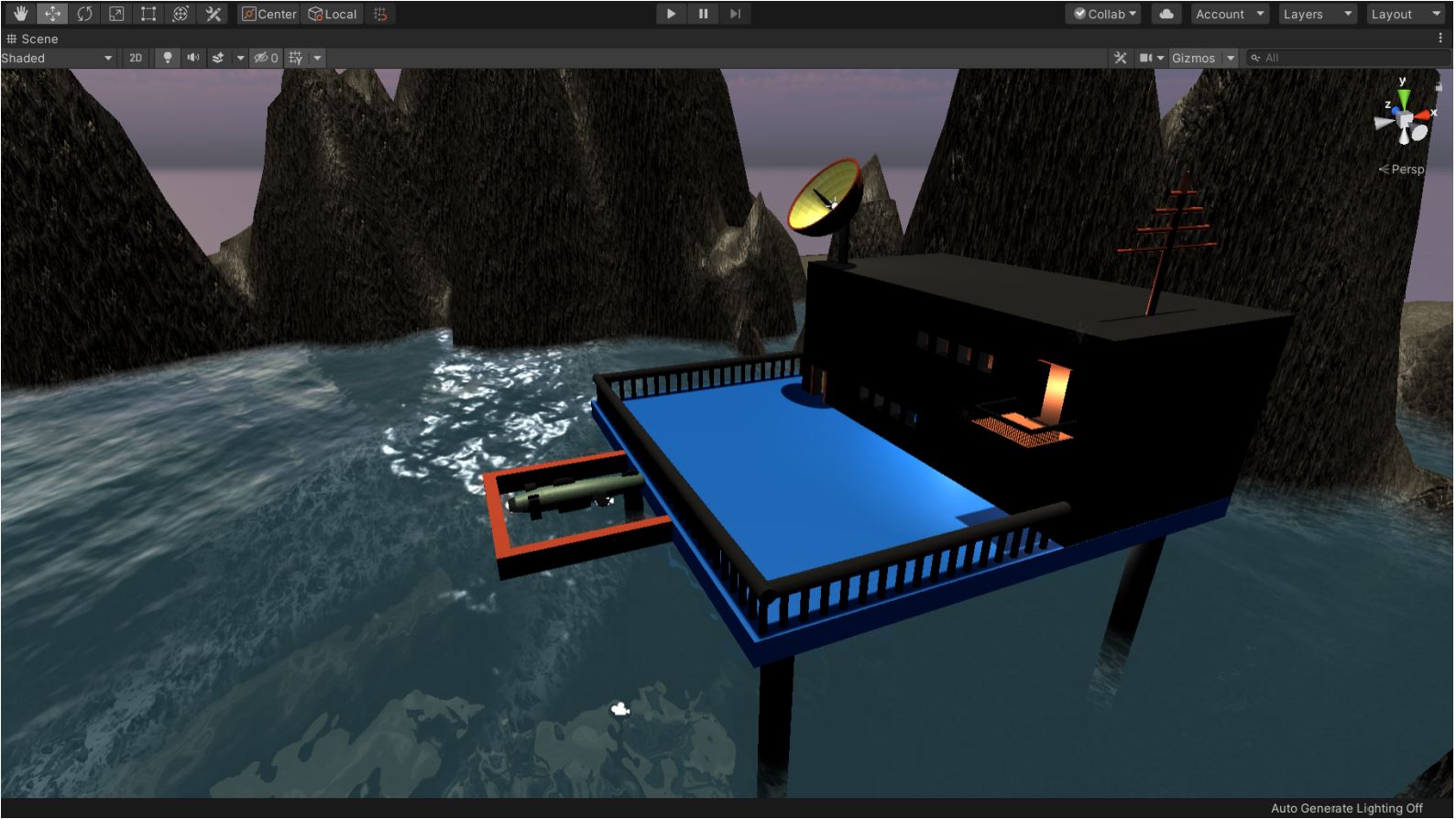
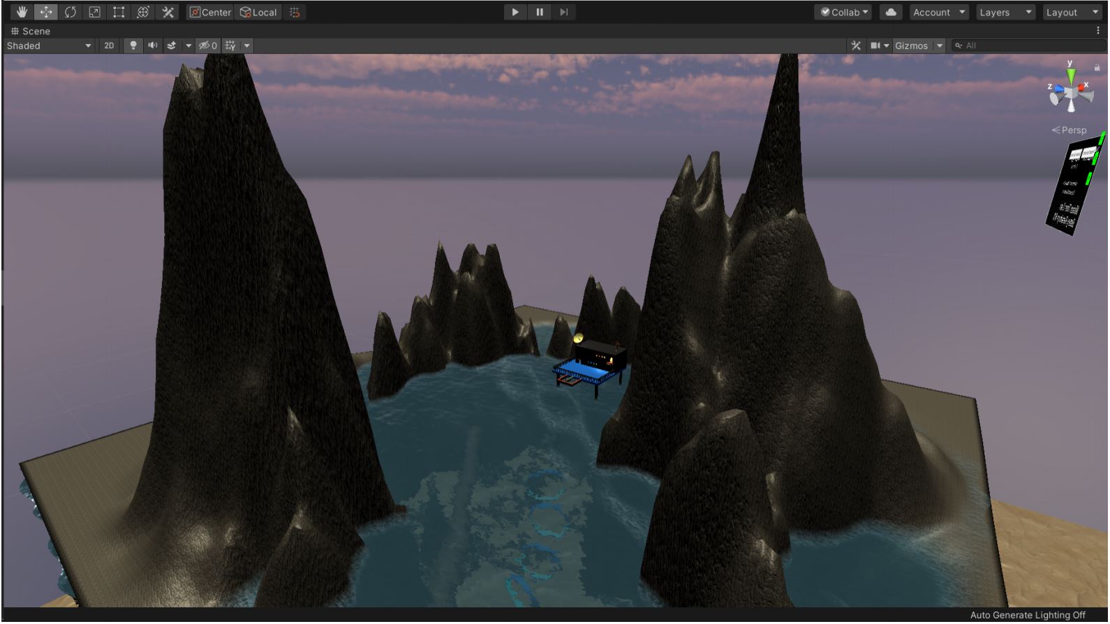
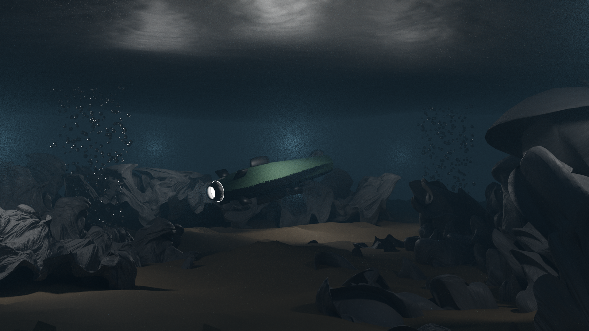
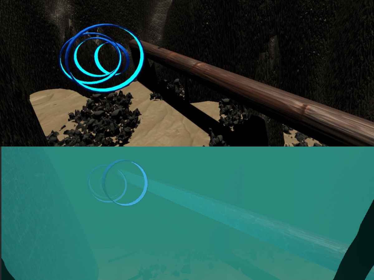
The Scene of the Simulator consists of hilly terrain with water-filled in the form of a lake. The water contains a pipe with a leak and four gates. The scene also contains a control station that harbors the AUV. The seabed is a separate object used both for texturing purposes as well as a reference object for various functions involving depth information. The following images display the Scene of the Simulation.
Along with functionality, aesthetics also play a major role in the simulator. We have created the seabed using simplex noise and custom-built shaders are used to simulate the underwater environment. A distortion effect is added to the camera view to depict the light distortion that occurs when the water is moving, as well as underwater fog. Light diffusion effects are also added to simulate how sunlight diffuses through the water and falls on underwater objects.
The Control Station
The Terrain
The Underwater Scene
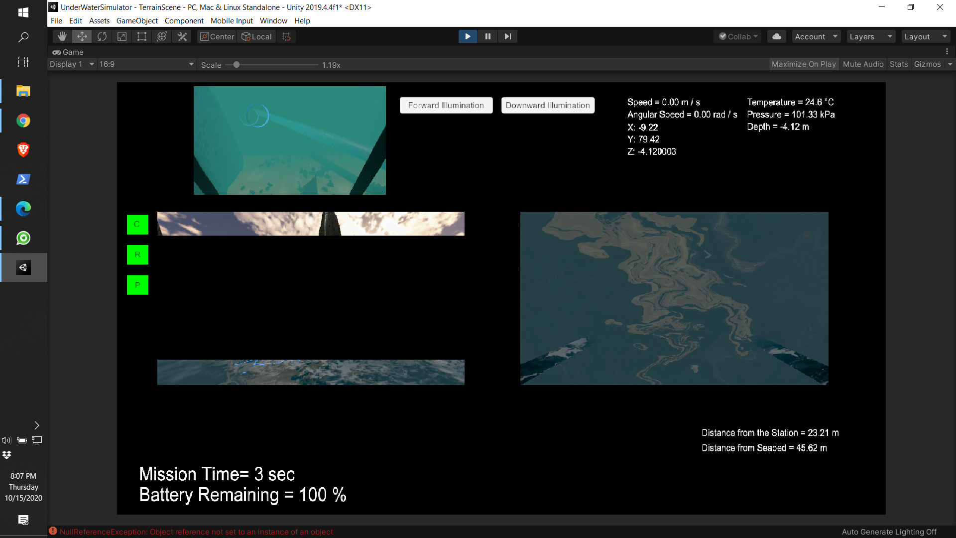
The User Interface
The User Interface (UI) allows the operator to monitor the state of the vehicle and help them to control the UUV. The layout of the UI is shown in the following image
The Simulator
The simulation starts with the AUV attached to the control station ready for the launch. As soon as the user presses ’R’, the AUV is released from the station into the water. From here, the operator has to control the 6 degrees of freedom of the AUV to find the pipeline. The operator uses two camera views along with other sensor data as listed in the User Interface section, to control the vehicle. The degree of freedom and their controls are as follows: The AUV is is aligned with the pipeline and then follows it to find the leak. When the leak is visible in the downwards facing camera, we consider the leak to be found, the coordinates of the leak are marked, and then the AUV proceed towards gates suspended in the water, to better test the controls of the vehicle. Once we have crossed all the four gates, we consider the mission a success.
The vehicle experiences buoyant force according to its submerged volume. This is achieved by dividing the boat mesh into triangles and then calculating the number of triangles that are submerged, whether fully or partially, underwater. An upward force is applied to individual triangles and the cumulative effect of those forces is seen as the buoyant force on the body. But to use this force, we need a constant downward force from the vehicle’s thrusters to keep the AUV stabilized at a depth, which can only be achieved after a control system integration from ROS side. So to get the desired effect when using Unity3D alone, gravity is switched off.
Blender
All the Prefabs of the simulation were modeled using blender. This served as a great learning experience in both the blender environment and Unity3D. Objects are exported as Filmbox (.fbx) file type from blender, so they can be imported into Unity3D. The objects behave differently in Unity once they are imported and therefore a little care is needed when using them. The major difference comes in the way the shaders built-in blender behave in unity, so sometimes new shaders were needed after the objects were imported into Unity.
The Sensors
The sensors to be deployed on the UUV are as follows:
- Two camera- Front facing and Downwards facing.
- Inertial Measurement Unit (IMU)
- Pressure Sensor
- Temperature Sensor
- Proximity Sensor
- Navigation Lights
Robot Operating System Link to heading
This project has been tested on ROS Melodic, Noetic, and ROS 2 Eloquent. This section will deal with the instructions for the ROS side of the project. The RosBridgelibrary used on the ROS side is part of rosbridge_suite. We use a WebSocket to pen a connection, to which Unity connects. The exchange of information happens over this connection including all the video feeds as well as the parameters.
For ROS 1
-
Install ROSBridge suite on your linux machine.
akash@unitymachine:~$ sudo apt-get install ros-<rosdistro>-rosbridge-suite -
Source your ROS distro and run the websocket launch file.
akash@unitymachine:~$ source /opt/ros/<rosdistro>/setup.bash
akash@unitymachine:~$ roslaunch rosbridge_server rosbridge_websocket.launch
This will also run ‘roscore’.
-
Check the host IP address in a new terminal using
akash@unitymachine:~$ hostname -I
Note: If you are running Unity and ROS on the same system, the IP address would be ‘ws://localhost:9090’
- Open a new terminal and source your ros distro. Then make a workspace with a package inside having rospy as a dependency and run the scipt in the ‘ROS’ folder of this repository.
For ROS 2
The rosbridge_suite currently does not support ROS 2 officially. But there is a pull request (https://github.com/RobotWebTools/rosbridge_suite/pull/493) to the repository for ROS 2 support. We use the contents of that pull request to setup the rosbridge connection for ROS 2.
- Clone the rosbridge_suite repository to your system.
akash@unitymachine:~$ git clone https://github.com/RobotWebTools/rosbridge_suite.git - Shift to the latest commit of the ROS 2 support pull request using GitHub CLI.
akash@unitymachine:~$ gh pr checkout 493 - Build the library on your system and source your ROS 2 distro.
akash@unitymachine:~$ source /opt/ros/eloquent/setup.sh akash@unitymachine:~$ cd rosbridge_suite akash@unitymachine:~/rosbridge_suite$ colcon build - Source the setup.bash of the rosbridge library.
akash@unitymachine:~/rosbridge_suite $ source install/setup.bash - Run the websocket script.
akash@unitymachine:~/rosbridge_suite $ ros2 run rosbridge_server rosbridge_websocket
RosBridge Library Link to heading
There are two Rosbridge libraries that come into play when using this project. One on the unity side and the other one on the ROS side. Both of them are named the same. For the sake of simplicity, I’ll be using RosBridgeUnity and RosBridgeRos to denote the library of Unity and ROS respectively.
What is RosBridge Library in general?
The documentation of the rosbridge_suite (i.e. RosBridgeRos) states “rosbridge provides a JSON interface to ROS, allowing any client to send JSON to publish or subscribe to ROS topics, call ROS services, and more. rosbridge supports a variety of transport layers, including WebSockets and TCP.”
In simpler terms, you can send data over a network to and from ROS using this library. This is how we use it in this project. We send data, which might include parameters, control inputs, or video feed, between Unity3D and ROS which enables us to use the Unity simulator as a substitute for actual hardware. This allows us to test all of our algorithms as if we are running them on the actual ROV itself. Thus saving us time and money, and it also reduces risks that experimental programs might pose on expensive hardware.
The RosBridgeUnity is a C# based library which serves as the other end of this exchange. It was forked from @MathiasCiarlo and @michaeljenkin who were using it on projects of there own. It comes with some primitive scripts to get the connection running and the user can then use them as a base for their own project. You can find the original repository here: https://github.com/MathiasCiarlo/ROSBridgeLib
More details on ROsBridgeROS can be found on the ‘ROS 1 and ROS 2’ page of the wiki. This section will focus on ROsBridgeUnity.
This project uses RosBridgeUnity to send video feeds, depth feed, and vehicle parameters from Unity to ROS and receives control commands from ROS. The setup includes using the ‘RosInitializer’ script to input the target IP address and call all the subscriber and publisher scripts in Unity. RosInitializer.cs also projects the camera feed to 2D textures so that it can then be transferred to ROS as a compressed image.
To use RosBridgeUnity in your Unity project, copy the RosBridgeLib folder to your Assets folder along with the ‘RosBFolder’ in the scripts folder which contains the required scripts to launch your connection.
Mapping Link to heading
Mapping the vehicle’s environment was at the core of the project. It is especially important because it will enable us to save the map and use it later for our digital twin implementation. So to test our mapping systems, the first step was to give our simulator mapping capabilities. Following that, Octomap was used to map and store the environment on the ROS side.
Unity3D SONAR Link to heading
The first task at hand was to emulate a multi-beam sonar in our Unity3D vehicle to send depth information over our ROSBridge. This was done using the Raycast method of the Physics package of Unity. The steps required for this implementation are as follows:
- Create a Raycast hit array for the number of rays you want.
- Check for the ray collisions with an object.
- If a collision occurs, save the distance to a depth array element.
- If not, then assign a large enough value to the element which will then be substituted for infinity by the ROS decoder for the /scan message.
        RaycastHit hit;
        Debug.DrawRay(auv.transform.position, auv.transform.right * -30);

        if (Physics.Raycast(auv.transform.position, auv.transform.right * -1, out hit, 30))
        {
            depthLog[320] = hit.distance;
        }
        else
        {
            depthLog[320] = 30;
        }
This concludes the Unity3D implementation, and we can now move on to the Octomap module.
Octomap Mapping Link to heading
As mentioned in the Octomap’s homepage - “The OctoMap library implements a 3D occupancy grid mapping approach, providing data structures and mapping algorithms in C++ particularly suited for robotics.” We use octomap to recreate the environment scanned by our underwater vehicle, and subsequently, save it to be used to future implementation. This is done in several steps which are outlined below.
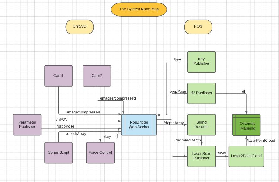
- By incorporating the position published from the Unity3D simulator, we publish the transform of the vehicle by using the tf2 library. This is then broadcasted by a tf broadcaster, to be used by our octomapping node later on.
- A string decoder subscribes to the decoded depth array sent from Unity3D and republish that data as a float array.
- The LaserScan Publisher uses the decoded dpeth float array to convert it into a laser scan topic. It also uses the field of view topic to get the angle of scan for the laserscan topic.
- The octomap mapping tool need the depth data as a point cloud. So we convert the laser scan to point cloud to and publish it over the topic /laserPointCloud
- Once we have our point cloud and transforms ready, we feed them into our octomap mapping node, where we can use rviz tool to visualize the recreated map.
- The final Node Map of the whole system is represented by the following figure
Unity3D Scripts Link to heading
A brief description of the scripts used is given below. Further documentation can be found within the scripts.
-
AUVControl: This script uses transform function to move the AUV body, disregarding its mass properties.
-
Buoyancy:
- BoatPhysics: This script is attached to the vehicle and find the extract information about the location of the meshes.
- ModifyBoatMesh: Generates the mesh that’s below the water.
- TriangleData: Send the triangle information to other Buoyancy scripts.
- WaterController: Extract information about the water and water level to send to the other scripts.
-
ButtonFunctions:
- Release the AUV from the control station when ’R’ is pressed.
- Control the button functions for the Front and Downward Illumination.
- Optional functions to switch camera view if the user doesn’t want two camera views on the screen.
-
Coordinates: Show the coordinates of the AUV and freezes them when ‘M’ is pressed to mark the Leak’s coordinates.
-
FogStart: Switches on Unity’s Fog when the vehicle’s position is below the water level. The color of the fog is preset in Unity settings.
-
ForceControls: Uses AddForce and AddTorque to make the vehicle move, thus providing a more realistic approach.
-
PauseGame: A pause menu for the simulator to give the user more control over the scene and easy access to the Main menu.
-
SeabedScript:
- Calculates Vehicle’s Angular and Linear Velocity and convert them to scalar their respective scalars i.e. Angular and Linear Speed.
- Calculates the Acceleration of the Vehicle.
- Calculates the vehicle’s distance from the seabed.
- Calculates the Vehicle’s depth, its surrounding Temperature and Pressure.
- Calculates the Vehicle’s distance from the control station.
- Controls the behavior of the Range warning, Proximity warning and the collision warning LEDs.
-
StartScreen: Script controlling the elements of the main menu including user input for IP address, port number, and mission timing. Takes these inputs and uses them in the simulator and redirects to the simulator screen when ‘Start’ is pressed.
-
StartUnderwater: Starts the underwater distortion effects when a particular camera goes below the water level. Also plays the background sounds when the vehicle goes underwater.
-
SwitchOffGravity: Used only when the Buoyancy scripts are not being used. Disables the gravity as soon as the vehicle enters the water, to simulate a simple underwater environment.
-
UIScript: Controls and Display the following UI elements:
- Speed
- Angular Speed
- Acceleration
- Temperature
- Pressure
- Depth
- Distance from the seabed
- Distance from the control station
- Remaining Battery
-
UnderWaterEffects: Controls the parameters for underwater distortion effects. Called by ‘StartUnderwater’ to activate the effects on cameras.
-
WaterAnim: Controls the caustic projection on object surfaces to create a lightening shift effect due to water.
RosBFolder Link to heading
- PoseSubscriber: Subscribes to a ‘pose’ topic which is then used by control scripts for movement and function controls.
- TwistPublisher: A base publisher that can publish pose data.
- DataManager: Controls the publisher script to publish the required information.
- downcamPublisher: Compressed Image Publisher for the downward-facing camera.
- frontcamPublisher: Compressed Image Publisher for the forward-facing camera.
- ImagePublisher: Standard compressed image publisher which is used to transfer station camera feed to ROS.
- ImageTransfer: Encode the video feed into a string message which can then be used to call the StringImagePublisher to publish the video feed as a string topic type.
- RawImagePublisher1: A base Raw Image Publisher.
- ROSInitializer: Initializes the Rosbridge connection using the IP address entered in the start screen. Also encodes video feed by first projecting it on a texture and then publishing that texture as a compressed image.
- StringImagePublisher: A base publisher for String topic type, used to transfer video feed as string message type.
Underwater Environment Link to heading
This section deals with creating a realistic underwater environment, which includes water surface, light diffusion effects, and fog effects. We will not discuss underwater distortion as that will involve shaders, which fall out of the scope of this section.
Setting Up the Environment Link to heading
We will first set up the environment using some simple shapes and Unity’s Standard Assets. The steps are as follows:
- Make a pool using 5 cubes by resizing them.
- Import Unity’s Standard Assets from the Asset Store, into the project.
- Go to Standard Assets -> Environment -> Water You’ll see two options. Both are just different versions, and what you choose depends upon your preference and how much resources do you have to spare to render water. In this project, we use Water4Advanced.
- Further go to Water4 -> Prefabs and insert the Water4Advance into the scene. Resize it according to the size of your pool. Note: Never scale it more than 2 times, or the waves will become choppy. Insert multiple instances of the prefab if you want to cover a larger area, each with a scale of 2 or lower.
- Set your camera (or cameras) at a good vantage position to observe the effects. You can have two cameras, one above the water and one below to better observe all the effects.
- Optional Duplicate your water prefabs, rotate them 180 degrees on the x-axis and move them just a little bit below the original ones to get better reflections once you are underwater.

Once this is done, we can now move on to add underwater fog to limit visibility.
Underwater Fog Link to heading
Once the vehicle or player is underwater, it becomes very clear that the scene doesn’t look realistic. It looks just like it does above water. So we will now add underwater fog. This is done by using unity’s own Fog in the Lightening Settings. But before that, we will add a player which can move in the scene.
- Add a platform for the player to walk on, which is connected to the pool.
- Add a capsule GameObject, which will behave as our body.
- Go to Standard Assets -> Characters -> FirstPersonCharacter -> Prefabs and add RigidBodyFPSController to the scene. Make it the parent of the Capsule that we added before, and make them overlap in position.
This is our player now. You can playtest it by playing Ctrl + P and moving around in the scene, or even jump in the water. You can delete the cameras, although they can still be used for observations.
- Go to Window tab -> Rendering -> Lighting and click on the Environment Tab. You can see the Fog settings (under Other Settings) there. This is where we will set the color of our fog. (You can give colors to all other assets too, for aesthetic effects)
- Check the box in front of the Fog option. This will switch on the fog. You will notice that the fog is greyish and it’s everywhere, including above water. We will control its activation with a script.
- Change the mode to ‘Linear’, which gives it a more realistic effect.
- Keep the Start position as zero and set the end position according to your scene. I am using 20.
- Set the color according to your preference. I am using a dirty green color to get a more algae infested water body.
- Once you are satisfied with your fog color and distance, uncheck the fog check box.
Now we will control it using a script.
- Import the Fogstart.cs script, from this project, into your project.
- Add this script to the camera component of the RigidbodyPlayer.
- Insert the Water prefab in the water level Column of the script in the Inspector Panel of the Camera.
This script checks whether the camera is underwater or not, and switches the fog on or off accordingly.

Our fog is now in place, and we can now move forward with underwater light distortion effects.
Underwater Diffusion Link to heading
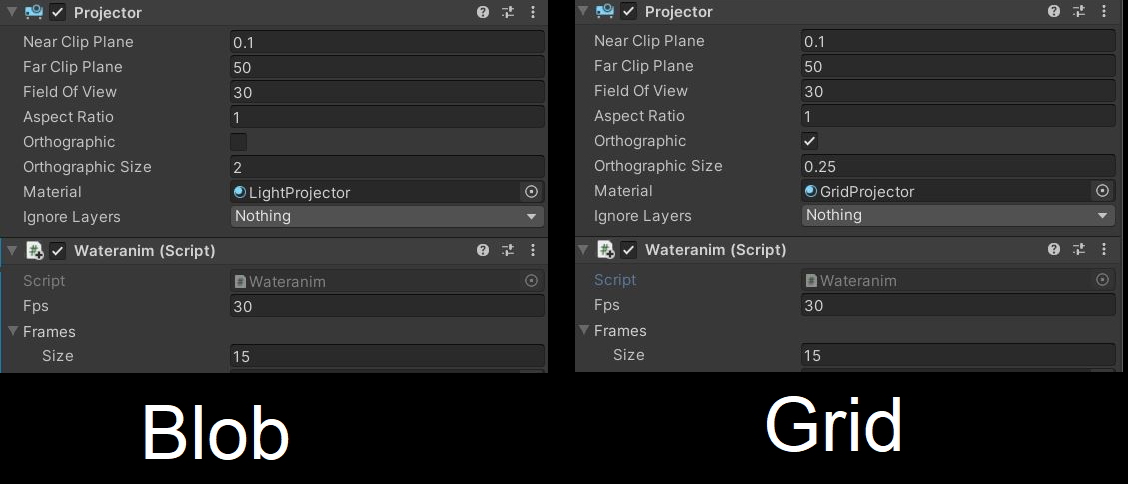
When light passes through the water’s surface, it diffuses and falls on the underwater surfaces in a continuously moving pattern. We will try to emulate this effect using caustics and projectors. A Projector allows you to project a Material onto all objects that intersect its frustum. We will use two projectors. Once is a blob light projector and the other one is a grid projector. The BlobLight projector will project from the water’s surface, while the grid projector will do it from above.
- Go to Standard Assets -> Effects -> Projectors -> Prefabs and add BlobLightProjector & GridProjector to the scene. Place the grid projector above the water surface, and the Blob light projector just below the surface.
- Import the WaterAnim.cs script from this project into your project and attach it to both the projectors.
- Import the Caustics folder to your projector, which contains the images that’ll be projected onto the surfaces.
- Set the settings for the projectors in the inspector panel as shown below
- Add the images inside Caustics to the boxes under the script inspector panel of both the projectors.
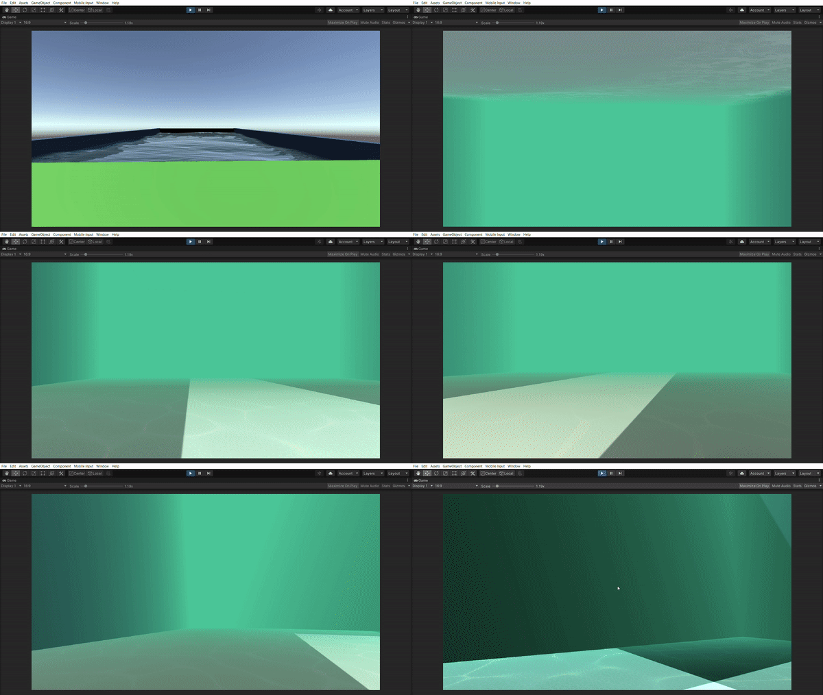
And that is how you create an underwater scene. You can insert several other objects in the scene according to your needs and create a custom controller for your player so that you can control it in all degrees of freedom when underwater. You can go through the documentation of this project to know more about how to do that. A sample barebones underwater scene can be found here.
